Hq notch filter without close-tolerance components circuit diagram Solved in the notch filter circuit shown in the figure, Mhz notch
Notch filter circuit. | Download Scientific Diagram
Notch filter (bandstop): what is it? (circuit & design)
4.5 mhz notch filter schematic circuit diagram
Notch filter circuit.Notch filter circuits homemade circuit simulation designing 50db efficient above most not details Filter notch circuit solved shown figure frequency response transcribed problem text been show has diagramNotch example.
Notch filter: the circuit’s diagram and the design formula – electronic60hz notch filter Notch filter circuit active stop band electrical4u transfer functionOp amp.

Notch filter 60hz circuit twin analog amplifiers
Notch circuit integratorNotch filter circuits with design details Notch filter circuit as an example.Notch tolerance components resistors capacitors reach within.
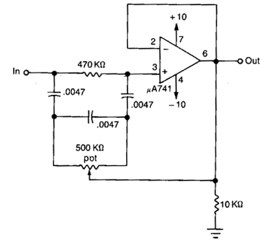
Simple notch filter uses an operational amplifierNotch filter and integrator circuit. Filter notch uses operational circuit amplifier audio tunable diagram simple applications gr nextNotch variable.

Variable notch filter circuit
Filter notch twin high circuit active audio 60hz schematic 60 filters hz simulation op amp network am circuits gr nextBuild an audio notch filter 2 .
.